March 14, 1994: Headlines: COS - Peru: Engineering: Space: Ground Stations: Project Management: NASA: Personal Web Page: Peru RPCV Hugh Pickens was AlliedSignal Project Manager on NASA's GRO Remote Terminal System (GRTS) Project
Peace Corps Online:
Directory:
Peru:
Peace Corps Peru:
The Peace Corps in Peru:
March 14, 1994: Headlines: COS - Peru: Engineering: Space: Ground Stations: Project Management: NASA: Personal Web Page: Peru RPCV Hugh Pickens was AlliedSignal Project Manager on NASA's GRO Remote Terminal System (GRTS) Project
Peru RPCV Hugh Pickens was AlliedSignal Project Manager on NASA's GRO Remote Terminal System (GRTS) Project
Peru RPCV Hugh Pickens was AlliedSignal Project Manager on NASA's GRO Remote Terminal System (GRTS) Project
NASA's GRO Remote Terminal System (GRTS)
In March 1992, NASA HQ challenged GSFC/Code 531 to propose a fast, low-cost approach to close the Tracking Data Relay Satellite System (TDRSS) Zone-of-Exclusion (ZOE) over the Indian Ocean in order to provide global communications coverage for the Compton Gamma Ray Observatory (GRO) spacecraft. GRO had lost its tape recording capability which limited its valuable science data return to real-time contacts with the TDRS-E and TDRS-W synchronous data relay satellites, yielding only approximately 62 percent of the possible data obtainable. To achieve global coverage, a TDRS spacecraft would have to be moved over the Indian Ocean out of line-of-sight control of White Sands Ground Terminal (WSGT). To minimize operations life cycle costs, Headquarters also set a goal for remote control, from the WSGT, of the overseas ground station which was required for direct communications with TDRS-1. On August 27, 1992, Code 531 was given the go ahead to implement the proposed GRO Relay Terminal System (GRTS). This paper describes the Remote Ground Relay Terminal (RGRT) which went operational at the Canberra Deep Space Communications Complex (CDSCC) in Canberra, Australia in December 1993 and is currently augmenting the TDRSS constellation in returning between 80-100 percent of GRO science data under the control of a single operator at WSGT.
On March 14, 1994, NASA announced the opening of a new, remote ground station in Tidbinbilla, Australia, called the GRO Remote Terminal System, to receive scientific data from the Compton Gamma-Ray Observatory (GRO) via a Tracking and Data Relay Satellite (TDRS) that was moved into position over the Indian Ocean.
The decision to build the ground station and devote a TDRS to the Compton GRO came after the observatory's tape recorders failed, restricting transmission of scientific data to real time only. Since Compton was compatible with TDRS, this ground station option was feasible. An on-orbit repair of Compton GRO was an alternative, but would have been much more costly.
"While the new ground station is devoted to Compton at this time, it has the potential for use by other Earth-orbital spacecraft. The TDRS system was designed to operate with all the TDRS spacecraft in view of a single ground station. As a result, coverage could not be provided in a small region on Earth -- the so-called Zone of Exclusion over the Indian Ocean.
"With activation of this ground facility, the TDRS system can, for the first time, provide global coverage," said Charles Force, Associate Administrator, Office of Space Communications, NASA Headquarters, Washington, D.C.
Work on the station was completed in a relatively short time and within its $12 million budget. Work began in September 1992 to implement a remotely controlled terminal at an existing NASA site and was a cooperative effort between the Australian Space Office and NASA
"We're very pleased that this project came in on budget and on time and that we are able to collect additional significant data from Compton in a cost-effective manner," said Frank Stocklin, Head, Radio and Frequency Interface and Mission Analysis Section, Goddard Space Flight Center (GSFC), Greenbelt, Md.
With GRO tape recorders not working, the observatory had been able to relay only slightly more than half of the science data it collected, because it could not point at a TDRS at all times. While coverage had been about 65 percent of each orbit, scientists could not collect that percentage of data because Compton's instruments had to be turned off during the part of the orbit when the spacecraft passed through the background radiation caused by the South Atlantic Anomaly.
"That had represented a significant obstacle to the scientific teams, even though we have been able to collect more science than expected," said Goddard's Dr. Neil Gehrels, Compton Project Scientist. "Now with the ground station and the TDRS, we're back where we want to be."
With a TDRS devoted to Compton, scientists will be able to collect about 30 percent more science. In addition, engineers will be able to keep better tabs on the health of the $500-million observatory, launched from the Space Shuttle Atlantis (STS-37) on April 5, 1991.
"It's difficult to place a dollar value on the additional science data obtained in this effort," Stocklin said, "but the restoration of data recovery capability is similar to that done for the Hubble Space Telescope and marks the second successful recovery of a major NASA observatory."
TDRSs receive data from Earth-orbiting satellites and re- transmits the data to a ground terminal in White Sands, N.M. Data from the Compton will be relayed from TDRS-1 to Tidbinbilla to an Intelsat satellite to a West Coast location and then routed to White Sands. Data then will be distributed to scientists around the world. Control of TDRS-1 and this highly automated ground terminal remains at White Sands, N.M., marking the first time NASA is controlling an out-of-view TDRS from that location.
Launched in 1983, TDRS-1 was the first satellite in the TDRS system and was operating beyond the end of its design life of 8 years when it was moved over the Indian Ocean. TDRS-1 had been located at 171 degrees west longitude over the Pacific. It is now at 85 degrees east longitude, in view of the Tidbinbilla ground station.
"In its current use, TDRS-1's useful life may be extended to the end of the decade and perhaps beyond," Stocklin said.
GRTS - An Experience of a Lifetime
by Frank Stocklin - Goddard Space Flight Center
The Gamma Ray Observatory (GRO), launched in April 1991, was performing as designed until it became obvious in 1992 that both of its onboard tape recorders would fail, thereby reducing recovery of valuable science data to real-time only at a reduced data rate of 32 kbs (versus 512 kbs during playback). Under these conditions, only approximately 62-percent (worst case GRO attitude) of data could be recovered with the existing 2-TDRS constellation. In March 1992, the MO&DSD was requested to study approaches to solve this problem utilizing any combination of ground or space resources.
By using the Communications Link Analysis Simulation System (CLASS), analyses were completed which quickly ruled out a ground station solution (i.e. high-cost with a relatively small increase in additional coverage) but indicated a TDRSS solution could produce a 33-percent increase in coverage - even under worst case GRO attitude conditions (i.e. 0-degree boom angle). To achieve this, a TDRS spacecraft would have to be moved and located somewhere over the Indian Ocean. Figure 1 depicts the percentage of coverage versus TDRS location in longitude degrees and is the result of a large number of computer runs to develop a reliable statistical result. Notice that using the two-TDRS solution at 174-degrees and 41 degrees west, approximately 62-percent coverage can be obtained. Adding a third TDRS within view of the White Sands Ground Terminal (WSGT) produces an additional 6-percent of coverage. To obtain the maximum possible, an additional TDRS has to be located at approximately 80-degrees east longitude. This would produce in excess of 82-percent coverage which is a 33-percent increase relative to the 62-percent baseline (actually full 100 -percent coverage is possible depending on the attitude of GRO, which is science dependent, and also the blockage of the GRO high-gain antenna to TDRSS). Since these "optimum" locations were not in view of the WSGT control facility, the problem of locating this ground control facility had to be solved. The Deep Space Network (DSN) sites at Madrid, Spain and Canberra, Australia were obviously the prime candidates. As can be seen from Figure 1, the Madrid and Canberra locations (to produce a 10-degrees elevation to the TDRS spacecraft) were not far from the "optimum" position. The Madrid solution suffered an approximate 2-percent penalty in coverage loss due to the South Atlantic Anomaly (SAA) effects on the GRO instruments (i.e. the instruments had to be turned off while flying through the SAA region). Other ground locations consistent with the maximum coverage point wee examined (e.g. east Africa) but were discounted primarily because they were not under direct NASA control. The Australian solution was near the maximum geometric point, had a stable political and economic environment, and had a NÐSA-like culture/expertise. From a geometric viewpoint, the west coast of Australia and central areas were preferable. The east coast had a existing NASA facility at Canberra with the requisite infrastructure.
A site survey team consisting of the Australian Space Office (ASO) and NASA visited five sites throughout Australia and considering various criteria such as existing infrastructure, accessibility to long-haul communications, transportation accessibility, etc., the site at the Canberra Deep Space Communications Complex (CDSCC) was recommended and selected.
The CDSCC location did have some negative geometric features. A lower than desirable elevation angle to the optimum TDRS location at 81-degrees east required a shift to the 82-degrees east location (a subsequent shift to 85-degrees east was necessary to accommodate the high inclination excursion of the F1 TDRS throughout the next 10 yeas). As can be seen from Figure 1, this shift did not significantly reduce the percent coverage. A second problem was related to the inability of the F1 to point its space-ground -link antenna far enough southward to cover CDSCC. After extensive analysis and testing, a 2-degree south roll bias solution was selected and the necessary software changes to the WSGT were initiated.
During the summer of 1992 implementation studies for the supporting ground terminal were completed. Because the "best science" would be obtained within the next few years, speed in implementation was a high priority. Limited and fixed funding dictated maximum use of existing design and equipment. Protection of an aging and somewhat sensitive F1 required redundancy in the implementation. Despite the fact that F1 is near the end of its design life of 10 years, its remaining functionality meets the specific needs for the GRTS application. The mandate to have minimal annual maintenance and operations costs required some form of automation. With these requirements, the GRTS Project was started on September 1, 1992. A 13-month schedule to completion, a $12.1M million fixed budget, and a 10-year lifetime wee the primary programmatic constraints.
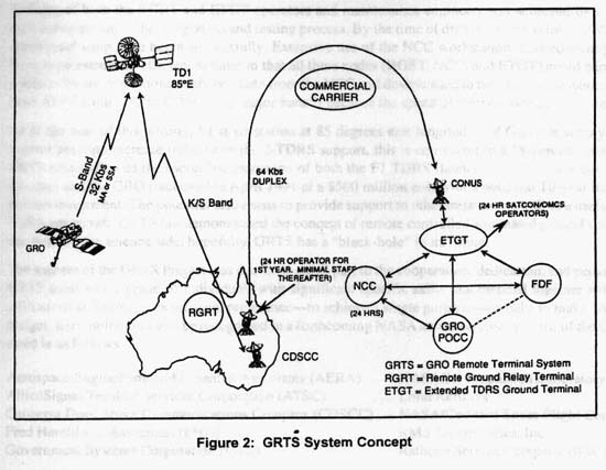
The GRTS system concept is shown in Figure 2. The GRO spacecraft radiates 32 kbs data to the F1 located at 85-degrees east longitude (this is in addition to support from the nominal two TDRSs). F1 receives the data using either the Multiple Access (MA) of Single Access (SA) capability. The data is transmitted to the Australian terminal called the Remote Ground Terminal (RGRT). Using dual 64 kbs Nascom lines, the data is sent to the WSGT, specifically to the GRTS dedicated Extended TDRS Ground Terminal (ETGT), and then to the GRO data processing center at GSFC. Telemetry, Tracking, and Command (TT&C) for the F1 flow from/to the ETGT continuously, also through the 64 kbs lines. The satellite controllers at WSGT are in complete control of the F1 spacecraft as well as the RGRT. The Network Control Canter (NCC) at GSFC has overall scheduling and management control. The GSFC Flight Dynamics Facility (FDF) performs its usual tracking and orbit determination function.
The node at RGRT contains the antennas, receivers, transmitters, and associated computer controls. Much of the equipment was placed in the existing DSS-46 building. To ensure minimal impact to ongoing operations at CDSCC, all of the RGRT equipment was placed in special RFI-tight racks. The high-powered transmitters were placed in newly constructed buildings, one S-Band and a separate K-band, to minimize self and external interference. Special attention was paid to the grounding process to preclude ground loops and possible impact to ongoing operations. The RGRT antennas were located so as to minimize impact to any current or future place at the CDSCC. A required MA calibrator, which radiates at 2287.5 MHz, was moved to a remote location approximately 2 km from the prime site and behind a hill to minimize interference to any sensitive (i.e. low-signal level) operations at CDSCC. All of the construction was performed by the CDSCC in 4 months. This consisted of two antenna pads in difficult terrain, two new S-band/K-band transmitter buildings, extensive cable trays and grounding, and a 2 km fiber cable run to the remote calibrator site - truly an amazing effort in that amount of time.
The other major node at ETGT contains all of the command and telemetry processing and unique software for the F1, the spacecraft controller personnel, and the interfaces to the GSFC for GRO data, the NCC, and the FDF. As with the other TDRS spacecraft, complete control still exists at ETGT. The uniqueness here is that it is a remote control operation of an out-of-view TDRS. The entire GRTS is connected by redundant Nascom 64 kbs lines from/to CDSCC to ETGT. Through these lines flow 8 kbs digital voice, TDRS telemetry and command data, e-mail, RGRT status, and GRO 32 kbs data. Automatic failover to a single 64 kbs lines in case of failure of one line is included.
To achieve the minimal operations staffing requirement, a distributed computer system, namely, the Operations Monitor and Control System (OMCS) was implemented. This consists of identical workstations at each of the primary nodes, (RGRT, ETGT and NCC), at which complete status and control of the RGRT can be exercised. That is, an operator at ETGT has complete knowledge of all RGRT equipment and can effect failover to redundant chains if necessary. RGRT maintenance is performed by two CDSCC engineers on prime shift (exigencies at other times are handled by call-in or other CDSCC personnel). Currently, there is a single round-the-clock operator at CDSCC. The OMCS consists of an existing Current off-the-shelf (COTS) software shell with customized interfaces to each of the GRTS components. A series of window-like screens with mouse selection allows visibility and selectivity to any part of the RGRT from any of the nodes. The net result is a remote controlled automated site that can control an out-of-view F1 with minimal staffing.
To achieve the very ambitious schedule constraint, maximum use of existing equipment was incorporated into the RGRT design. Essentially, all of the TT&C equipment was obtained from existing resources at GSFC. Redundancy in design was used throughout the GRTS to the extent that it was feasible and practical. Additionally, the TT&C equipment was identical to the existing equipment at CDSCC so that the training, repair, and logistics were already basically in pace. Mux/Demux units at either end of the Nascom lines were current COTS equipment each with automatic failover capability built in. The command validation units were a NASA in-house design and were customized for the TDRSS command signal structure. To receive and demodulate the GRO 32 kbs MA and SSA signals, a receiver developed from the TDRSS user RF Test Set (TURFTS) was used. It required modification to interface with the MA equipment and also some threshold extension to work at lower signal levels. Maximum use of existing Second TDRSS Ground Terminal (STGT) designs was made. The entire MA system and some additional RF components were brought from the same vendors. All of the remaining hardware, including the 10M S-band antenna and the 4.6M K-band antenna were procured externally using COTS designs.
The procurement strategy and process was very critical in attempting to meet the imposed schedule. The Raytheon Service Company (RSC) was used as the procurement agent for NASA. Technical support was provided by the AlliedSignal Technical Services Corporation. (ATSC) and NASA. The entire procurement process including specifications, solicitation, and negotiation was completed by January 1993. The 120-day delivery (or less) requirements was imposed on most vendors (except the MA) and the critical long-lead components were incentivized to ensure on-time delivery. Overall, this was a successful strategy. In the specific case of the MA equipment, it produced an early delivery which enabled the GRTS MA capability to be available 2 months ahead of the scheduled date. This was extremely significant in that it allowed testing of the MA capability prior to the F1 drift (drift is the moving of the F1 spacecraft from its nominal 171 degrees west location to the new 85 degrees east location). The 73-day trip started on November 29, 1993 and completed on February 9, 1994 and allowed GRTS to provide MA support to the GRO starting in late November and throughout the 73-day F1 drift. Monthly meetings between GRTS team and each of the more critical vendors allowed early detection/correction of schedule and technical problems. Numerous telecons were also helpful to work not only technical issues, but to make each vendor a part of the GRTS team. There were multiple occasions where this team relationship helped resolve thorny technical interface problems.
To further support the aggressive schedule, a transportation strategy was developed by RSC which had a goal of 169 hours of transit time from the vendor's dock to CDSCC. This goal was achieved for about 95-percent of the 434 pieces/53 tons of equipment shipped with essentially no damage except a 20-cent switch. This logistical success was primarily due to excellent RSC planning and coordination with ATSC and CDSCC.
Another critical decision was made to meet the schedule and that was to perform the Integration and Test (I&T) totally at the CDSCC (versus doing it at GSFC). This had the potential of saving 3-4 months of schedule but it had high risk because of the geographic distance from GSFC and the various vendors. This was mitigated by increasing the skill and staffing of the integration team from GSFC and WSGT, having specific vendor support travel to CDSCC, and by the excellent CDSCC resident expertise. As problems arose during the I&T process, expert were brought in for resolution. Overall assessment of this remote I&T approach is judged as a definite success although somewhat stressful. Figure 3 shows the integration team at work assembling the 20M S-band antenna. Figure 4 shows the completed K- and S-band antennas and the associated transmitter buildings.
Since the MA equipment was a clone of the STGT MA equipment, the original plan was to bring the GRTS MA equipment through STGT for final testing prior to shipping to CDSCC. This was the minimum risk approach but would have incurred an approximate 1-2 month schedule cost. Because we had previously run interface tests with the TURFTS receivers, and also had very successful acceptance tests on the MA equipment, the decision was made to ship directly to CDSCC with a staff of both GRTS and STGT personnel. Within a 2-week period after the MA equipment was on site, the first successful MA contact occurred-albeit a short 5-minute pass on October 5-but very significant because it would enable MA support to GRO during the entire drift period; the first operational MA contact occurred on December 6, 1993.
Training of both the RGRT and ETGT operators and maintenance engineers was achieved by a combination of classroom presentations and their participation in the integration and testing process. By the time of drift in late November 1993, everyone was sufficiently trained to enable operational support to begin successfully. Extensive use of the NCC workstation allowed testing and software development/correction to be done in an extremely efficient manner in that all three nodes (RGRT, NCC, and ETGT) could participate in real time as testing progressed and minor software corrections could be made from the NCC and downloaded to their other node workstations. Major software updates used Internet from ATSC Columbia to CDSCC- a major benefit because the speed of transmission allowed new software to be infused daily as necessary.
As of the date of this writing, F1 is on station at 85-degrees east longitude and GRTS is supplying approximately 20 contacts/day for a 17-percent absolute increase (relative to the 2-TDRS support, this is equivalent to a 28-percent relative increase). In addition to this success, the GRTS effort allowed the useful life extension of both F1 TDRS (launched in 1983 at a cost of $100 million and designed for a 10-year lifetime) and the GRO (launched in April 1991 at a $500 million cost with a potential 10-year lifetime) - a very significant return for a $12.1 million investment. The potential also exists to provide support to other missions as well as a useful location for future aging but still functional TDRS spacecraft. GRTS has demonstrated the concept of remote controlled automated ground stations and can be the prototype of other future designs. On the science side, hopefully, GRTS has a "black-hole" in its future.
The success of the GRTS Project was due in no small part to the cooperation, dedication, and personal sacrifice of the many team members. The GRTS team was a group of individuals with significant specific skills that blended together with a single purpose - regardless of company affiliations and sometimes personal preference - to achieve a single purpose - namely, to make GRTS work and complete it on time and within budget. Each individual will be recognized in a forthcoming NASA award ceremony. A list of the corporate names from which these individuals came is as follows: Aerospace Engineering and Research Associates (AERA), AlliedSignal Technical Services Corporation (ATSC), Canberra Deep Space Communications Complex (CDSCC), Fred Herold and Associates (FHA), Government Systems Corporation (GTE), NASA/Jet Propulsion Laboratory, Loral AeroSys, NASA/Goddard Space Flight Center, RMS Technologies, Inc., Raytheon Service Company (RSC), Stanford Telecommunications (STel), TRW, UNISYS Corporation.
Return to Projects Page here.

Some postings on Peace Corps Online are provided to the individual members of this group without permission of the copyright owner for the non-profit purposes of criticism, comment, education, scholarship, and research under the "Fair Use" provisions of U.S. Government copyright laws and they may not be distributed further without permission of the copyright owner. Peace Corps Online does not vouch for the accuracy of the content of the postings, which is the sole responsibility of the copyright holder.
Story Source: Personal Web Page
This story has been posted in the following forums: : Headlines; COS - Peru; Engineering; Space; Ground Stations; Project Management; NASA
PCOL11407
04
.